Appendix
Modules
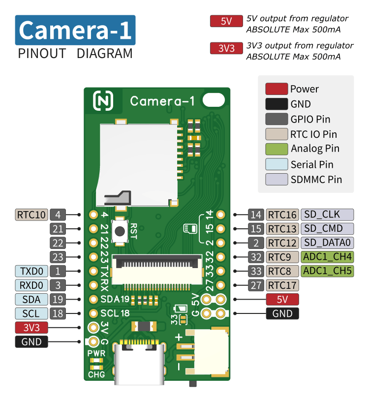
Camera-1 (Node-Matrix)
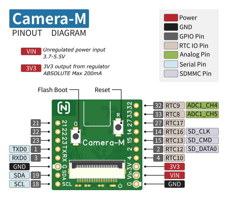
Camera-M (Node-Matrix)
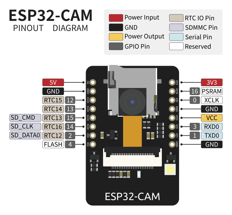
ESP32-CAM (Ai-Thinker)
GPIO12 Port
GPIO12 of the ESP32 chip is a Strapping pin. During system reset/power-up, the level of the Strapping pin will change the system boot mode or configuration. The level of the GPIO12 pin determines the output voltage of the VDD_SDIO pin during reset. As described in the ESP32 datasheet, if GPIO12 is low during system reset, VDD_SDIO outputs 3.3V; if it is high, VDD_SDIO outputs 1.8V.
If the module uses VDD_SDIO output as the power supply for external Flash or PSRAM chips, an incorrect GPIO12 level will cause the chip to malfunction. For example, the GPIO12 of the ESP32-CAM (Ai-Thinker) module must remain low during reset. Therefore, GPIO12 cannot be directly used as an I2C pin (with a pull-up resistor).
By modifying the ESP32 chip's eFuse bits, you can set a fixed output voltage for VDD_SDIO, making GPIO12 a normal GPIO port. Modifying the eFuse bits requires using esptool. See the official documentation for installation:
https://docs.espressif.com/projects/esptool/en/latest/esp32/
Steps to modify the eFuse bits:
Connect the module via USB serial port, reset the module to bootloader mode (keep GPIO0 low during reset).
Check the current eFuse data using the
espefuse.pycommand (replace COMx with the actual serial port):espefuse.py --port COMx summary
VDD_SDIO determined by GPIO12 Set VDD_SDIO fixed output to 3.3V:
espefuse.py --port COMx set_flash_voltage 3.3V
set_flash_voltage 3.3V espefuse.pywill prompt you to enterBURN(uppercase) for confirmation before modifying the eFuse.After successful modification, Check the eFuse data again (summary):

VDD_SDIO set to 3.3V by efuse
eFuse bits cannot be recovered after modification, please operate with caution.
FileZilla Server
FileZilla Server is a free FTP/FTPS server for the Windows platform.
Download address: https://filezilla-project.org
Installation and configuration:
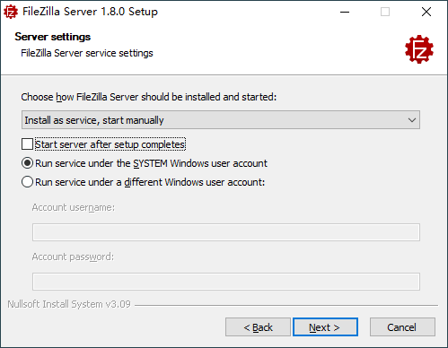
Download and run the installer. In the Server settings interface during the installation process, select the service startup method. For testing purposes, you can choose manual mode, and on the next page, select the console to start manually.
Service startup method After completing the installation, the FileZilla Server program group in the start menu is shown below. Start/Stop FileZilla Server need to be run as administrator (right-click > More > Run as administrator).

FileZilla Server program group Run Start FileZilla Server as administrator. Then run Administer FileZilla Server to open the console and connect to FileZilla Server.
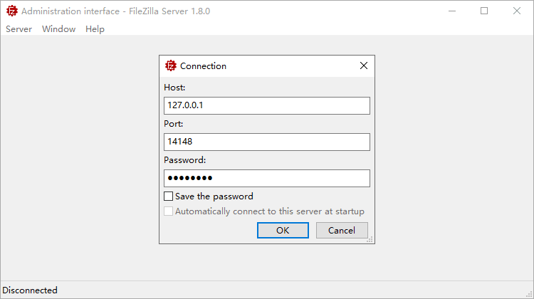
Connect to FileZilla Server In the console interface, click the menu Server > Configure... to open the Settings for server dialog. Configure the settings as follows:
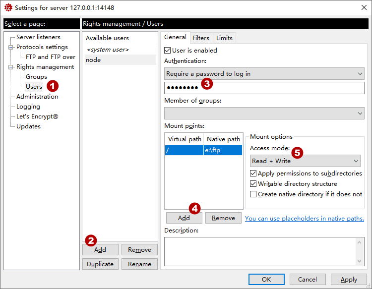
FTP Server Settings - Select the page: Rights management > Users
- Click the Add button to add an FTP user (node).
- Select the newly added user, and set the FTP access password.
- Add the FTP local path for the user.
- Set read and write permissions for the path.
After completing the settings, please check the Windows firewall rules: Allow TCP 21 inbound connections and TCP 20 outbound connections.
Save Video Stream
The ffmpeg tool can encode the MJPEG video stream output by Node-Camera into H.264 format for saving.
Download the ffmpeg tool from ffmpeg.org. Here, only
ffmpeg.exeis needed, ensure it is accessible from the command line. (Add to the Path environment variable or copyffmpeg.exeto the working directory)Execute the following command in the working directory (replace
${host}with the actual IP):ffmpeg.exe -f mjpeg -use_wallclock_as_timestamps 1 -i http://${host}:81/stream -c:v libx264 -crf 23 node.aviThe above command saves the video stream as
node.avi. The option-crfadjusts the video compression quality, with a value range of0~51(smaller values mean higher quality).
ffmpeg reference: https://ffmpeg.org/ffmpeg.html
Error Codes
System error codes reference:
| Code | Description |
|---|---|
| 0x50001 | ERR_UNAUTHORIZED |
| 0x50002 | ERR_INVALID_SETTINGS |
| 0x50003 | ERR_INVALID_PRESETS |
| 0x50004 | ERR_BAD_DATA |
| 0x50005 | ERR_BUF_INSUFFICIENT |
| 0x50006 | ERR_CRC_FAILED |
| 0x50007 | ERR_BAD_REQUEST |
| 0x50008 | ERR_INTERNAL_ERROR |
| 0x50009 | ERR_SESSION_EXCEEDED |
| 0x5000A | ERR_INVALID_SOCKET |
| 0x5000B | ERR_SD_DISABLED |
| 0x5000C | ERR_SD_NOT_INIT |
| 0x5000D | ERR_SD_FS |
| 0x5000E | ERR_NO_FILE |
| 0x5000F | ERR_NO_PATH |
| 0x50010 | ERR_ACT_NOT_INIT |
| 0x50011 | ERR_ACT_QUEUE_BUSY |
| 0x50012 | ERR_CMD_DISABLED |
| 0x50013 | ERR_CMD_UNDEFINED |
| 0x50014 | ERR_CMD_BAD_PARAM |
| 0x50015 | ERR_INVALID_IO |
| 0x50016 | ERR_INVALID_CHANNEL |
| 0x50017 | ERR_I2C_NOT_CONFIGURED |
| 0x50018 | ERR_INVALID_DEVICE |
| 0x50019 | ERR_INVALID_ACTUATOR |
| 0x5001A | ERR_DUTY_EXCEEDED |
| 0x5001B | ERR_SERVO_NOT_INIT |
| 0x5001C | ERR_SERVO_END_POINT |