System Settings
The Settings page provides system settings and testing tools.
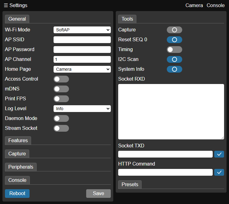
Settings Panel
The settings panel categorizes settings into different tabs (described below). Click the Save button to save the settings. The settings will take effect after a reboot (click Reboot). Rebooting will release network resources and may take a few seconds. The commands involved in this section will be explained in detail in Interfaces and Commands.
General
The General tab contains network and global settings.
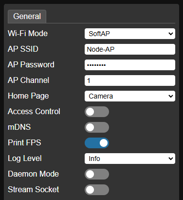
Wi-Fi Mode - Wi-Fi mode, default
SoftAP.Optional
SoftAP(provides 2.4GHz access point service) orSTA(accesses 2.4GHz network as a client). After selecting a mode, the panel will display the corresponding configuration options for setting the SoftAP’s broadcast SSID and password, or the STA's access SSID and password. In SoftAP mode, you can also specify the Wi-Fi channel (1~13). If the network environment has high interference, try switching channels.In SoftAP mode, the Node-Camera's IP address is fixed to
192.168.4.1. In STA mode, the Node-Camera's IP address is assigned by the connected router. You can find it by checking the startup information on the serial port or accessing the router's management interface.Home Page - System home page, default
Camerapage.Sets the default page when you access Node-Camera. Options:
Camera,Settings,SD Card,Console.Access Control - Access control switch, default off.
When access control is enabled and an access password (Access Code) is set, the system will verify the password when accessing Node-Camera functions or interfaces.
mDNS - Multicast DNS switch, default off.
When mDNS is enabled and an mDNS hostname (mDNS Hostname) is set, you can access the Node-Camera within the local network using
http://${hostname}.local, without needing to know the actual IP address. For example, if the hostname iscam, the access address will behttp://cam.local. This feature requires the operating system to support the mDNS protocol.SNTP Client - Network Time Client switch, default off.
This function is only valid in Wi-Fi STA mode and when SNTP services are accessible. After enabling SNTP, the Node-Camera will automatically obtain network time as the system time. Therefore, when using the capture function, the real capture time can be recorded.
Print FPS - Serial port frame rate output switch, default off.
When turned on, the serial port outputs real-time frame rate information.
Log Level - System log level, default
Info.System logs are output through the serial port. Optional levels:
Info,Warn,Error,None.Daemon Mode - Daemon mode, default off.
In daemon mode, you can choose to keep the "face detection" or "QR code scanning" algorithm running in the background, with the camera always on. When a face is detected or a QR code is recognized, the serial port outputs the results in real-time. In daemon mode, Node-Camera will disable access to the Wi-Fi video stream.
Stream Socket - WebSocket video stream switch, default off.
When the WebSocket video stream is enabled, Node-Camera provides a video interface through the WebSocket address
ws://${host}:81/stream, replacing the default HTTP video interfacehttp://${host}:81/stream.
Features
The Features tab contains settings for the built-in functions of Node-Camera.
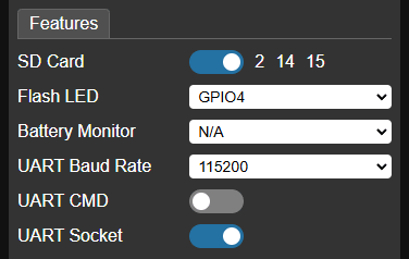
SD Card - SD card support, default off.
When SD card support is enabled, you can choose to save captured photos to the SD card (up to 4GB). The SD card uses GPIO2, GPIO14, and GPIO15 ports.
Flash LED - LED port selection.
If the system includes an LED light (built-in or external), you can set the GPIO port corresponding to the LED. After specifying this port, the flash command can control the LED switch.
The ESP32-CAM (Ai-Thinker) module's built-in LED is connected to GPIO4, and GPIO4 can be selected here.
Battery Monitor - Battery monitoring port selection.
This option is only available for modules that expose the ADC1 GPIO port. The ADC1 ports include:
GPIO Num ADC Channel GPIO36 ADC1_CH0 GPIO37 ADC1_CH1 GPIO38 ADC1_CH2 GPIO39 ADC1_CH3 GPIO32 ADC1_CH4 GPIO33 ADC1_CH5 GPIO34 ADC1_CH6 GPIO35 ADC1_CH7 After specifying the port, you need to set the voltage divider ratio for the voltage sampling point (Battery AD Ratio). Node-Camera determines the battery voltage based on the sampled voltage and the divider ratio to estimate the remaining battery level. A simple resistor divider circuit can be used for battery sampling.

Resistor divider In the figure, BAT is the battery voltage, and SP is the sampling voltage. The divider ratio is calculated as:
(SP / BAT) x 100%(take two significant digits)If BAT voltage is
4.16Vand SP voltage is2.03V, then:(2.03 / 4.16) x 100% ≈ 48.8%Taking two significant digits, Battery AD Ratio should be set to
49.Once the settings are complete, the real-time battery level will appear in the top navigation bar.

Battery level The Camera-1/M (Node-Matrix) module has a built-in voltage divider circuit for battery monitoring, which is connected to the GPIO33 (ADC1_CH5) port through a solder pad jumper (disconnected by default). Shorting the jumper will activate the sampling circuit.
I2C Driver - I2C driver support, default off.
This option is only available on modules that do not expose the image sensor's I2C-SCCB port. If the module already has the I2C-SCCB port of the image sensor exposed, Node-Camera directly uses this I2C port and no further configuration is needed.
When the I2C driver is enabled, specify the SDA and SCL ports.
- Some ESP32 strapping pins must be at a specific level during system startup. For example, the GPIO12 port should maintain a low level during startup, otherwise the VDD_SDIO output voltage may be abnormal. Therefore, GPIO12 cannot be directly used as an I2C port (with a pull-up resistor). See the GPIO12 port appendix for details on handling the GPIO12 port.
- The Camera-1/M (Node-Matrix) module has already exposed the I2C-SCCB port of the image sensor and does not need to be set.
UART Baud Rate - Serial port (UART0) baud rate setting, default
115200.UART CMD - Serial port command support, default off.
When enabled, the data received by the serial port will be parsed and executed as commands.
UART Socket - Serial-WebSocket bridge switch, default off.
When the Serial-WebSocket bridge is enabled, the serial port will be mapped to the WebSocket address:
ws://${host}/socket/uartOnce the client establishes a WebSocket connection with Node-Camera through this address, the client data sent over WebSocket will be passed through to the Node-Camera serial port output (TXD), and data received via the Node-Camera's serial port (RXD) will be sent to the client via WebSocket.
Capture
The Capture tab controls how captures are triggered and how captured photos are stored. Node-Camera supports captures triggered by hardware ports (external interrupts), network/serial commands, or periodic timing. Captured photos can be saved to an SD card and uploaded to an FTP server. The photo file names are incremented cyclically by sequence number (SEQ), with a maximum sequence number of 9999. The file name format is IMG_${SEQ}.JPG

Trigger - Trigger port selection.
Select a GPIO as the capture trigger port. The Trigger Type options:
Rising Edge,Falling Edge.Command Trigger - Command trigger switch, default off.
When the command trigger is enabled, captures can be triggered by sending commands through the network or serial port.
Timing Trigger - Timing trigger switch, default off.
When the timing trigger is enabled, you can set the timing interval (Timing Interval sec). While the system is running, you can start or stop the capture timer via command. When the timer is started, the system will trigger captures periodically at the set interval (in seconds).
Save to SD Card - Whether to save captured photos to the SD card, default off.
This option requires SD card support to be enabled.
Upload to Server - Whether to upload captured photos to the FTP server, default off.
When this function is enabled, you can set the server IP address (FTP Server), username (FTP User), password (FTP Password), and FTP path (FTP Path). For FTP settings, refer to Appendix FileZilla Server.
Peripherals
The Peripherals tab is used to configure available GPIO ports, PWM ports, and devices on the I2C bus. The GPIOs at the bottom of the tab indicate the currently available GPIO port numbers.
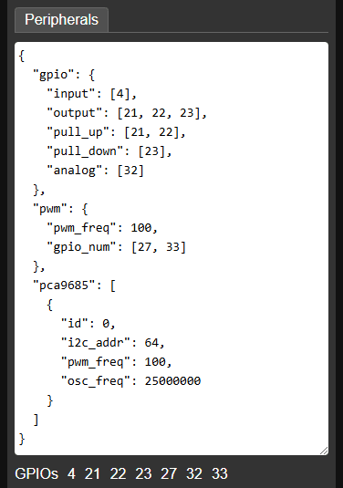
Peripherals configuration is defined in JSON format, with the template as follows:
{
    "gpio": {},
    "pwm": {},
    "pca9685": [ {} ]
}
Where the gpio, pwm, and pca9685 attributes define the GPIO ports, PWM ports, and PCA9685 modules (16-channel PWM expansion modules) mounted on the I2C bus, respectively. Each attribute's value is a corresponding JSON configuration object, explained below:
gpio - GPIO port settings.
Used to configure GPIO ports, so that GPIO ports can be read/written through commands. An example JSON is as follows:
json"gpio": { "input": [27], "output": [23, 33], "pull_up": [23, 33], "pull_down": [27], "analog": [32] }Attribute description:
input - List of port numbers configured as input, integer array.
output - List of port numbers configured as output, integer array.
pull_up - List of port numbers requiring internal pull-up resistors, integer array.
pull_down - List of port numbers requiring internal pull-down resistors, integer array.
analog - List of port numbers configured as analog input (must be ADC1 GPIO ports), integer array.
GPIO ports can be simultaneously configured as both input and output, allowing them to be read from and written to by commands.
pwm - PWM port settings.
Used to configure PWM ports. The pulse width (duty cycle) output of PWM ports can be controlled by commands. An example JSON is as follows:
json"pwm": { "pwm_freq": 100, "gpio_num": [21, 22] }Attribute description:
pwm_freq - PWM output frequency, integer.
gpio_num - List of port numbers configured as PWM output, integer array.
pca9685 - PCA9685 module configuration.
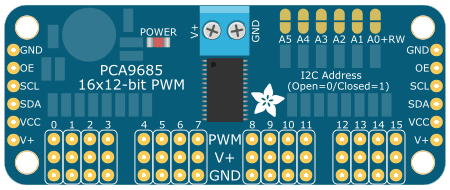
PCA9685 16-channel PWM expansion module If the system has exposed the image sensor I2C port, or has configured I2C Driver, Node-Camera supports mounting multiple PCA9685 modules on the I2C bus and allows control of the pulse width (duty cycle) output of each module’s port through commands. This configuration is an array, where each element represents a specific PCA9685 module. An example JSON is as follows:
json"pca9685": [ { "id": 0, "i2c_addr": 64, "pwm_freq": 100, "osc_freq": 25000000 } ]Attribute description:
id - Device ID (integer). Used to differentiate PCA9685 devices. This ID is used in subsequent configurations and commands to reference the correct device.
i2c_addr - Device I2C address (decimal integer). Each module should have a unique address.
pwm_freq - PWM output frequency, integer.
osc_freq - Crystal oscillator frequency, integer, optional. Used to calibrate the PCA9685 built-in oscillator frequency.
Console
The Console tab works with the Node-Camera video console page. It is used to configure the pan/tilt servos and the steering/drive actuators that correspond to the directional keys and joystick on the page. It also allows adding custom buttons to the console page.
Console configurations are defined in JSON format, containing different types of configuration objects to describe individual elements such as actuators and function buttons. First, we'll detail the JSON definition of each configuration object, and then introduce how to combine these objects into a complete Console configuration.
Actuators
The control page can operate two types of actuators: 1. servo; 2. DC motor.
Servo
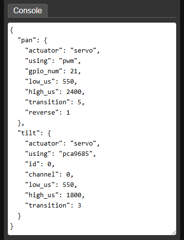
The servo is controlled by a PWM signal to adjust its angle or speed (for 360° servos). You can select the PWM GPIO port configured in the Peripherals tab, or the PWM channel of the PCA9685 module as the servo signal source. The JSON examples are as follows:
json// PWM GPIO signal source { "actuator": "servo", "using": "pwm", "gpio_num": 2, "low_us": 550, "high_us": 2400, "transition": 5, "reverse": 1 } // PCA9685 signal source { "actuator": "servo", "using": "pca9685", "id": 0, "channel": 0, "low_us": 550, "high_us": 2400, "transition": 5, "reverse": 1 }Attribute description:
actuator - Actuator type, string. For a servo, this value is
"servo".using - Signal source selection, string. Optional signal sources:
"pwm"- Use PWM GPIO port."pca9685"- Use the PWM channel of the PCA9685 module.
gpio_num - PWM GPIO port number, integer. Valid when the signal source is
"pwm".id - PCA9685 device ID, integer. Valid when the signal source is
"pca9685".channel - PWM channel number of the PCA9685 module, integer. Valid when the signal source is
"pca9685". The value range is0~15.low_us - Lower limit of the pulse width, integer value in microseconds, default
500. Used to control the lower limit of the servo angle or the maximum reverse speed of a 360° servo.high_us - Upper limit of the pulse width, integer value in microseconds, default
2500. Used to control the upper limit of the servo angle or the maximum forward speed of a 360° servo.transition - Transition time, integer value in seconds, default
1. Represents the time it takes for the servo to continuously turn from the lower limit angle to the upper limit angle, used to control the servo's smooth turning speed.reverse - Control reverse flag (
0/1), default0. Sets whether to reverse the direction logic of page controls or commands. When set to0, the up/right key or direction command increases the PWM pulse width (corresponding to the forward speed increase of a 360° servo); the down/left key or direction command decreases the pulse width (corresponding to the reverse speed increase of a 360° servo). When set to1, the above control logic is reversed. This flag is used to ensure the servo's action is consistent with the page or command logic, based on its installation direction.
DC motor
DC motors (such as N20 DC geared motors) are controlled by two PWM signals to adjust their speed and forward/reverse rotation. You can select the PWM GPIO port configured in the Peripherals tab, or the PWM channel of the PCA9685 module as the DC motor signal source. The JSON examples are as follows:
json// PWM GPIO signal source { "actuator": "motor", "using": "pwm", "gpio_num": [21, 22], "map": [100, 800], "reverse": 1 } // PCA9685 signal source { "actuator": "motor", "using": "pca9685", "id": 0, "channel": [1, 2], "map": [100, 800], "reverse": 1 }Attribute description:
actuator - Actuator type, string. For a DC motor, this value is
"motor".using - Signal source selection, string. Optional signal sources:
"pwm"- Use PWM GPIO port."pca9685"- Use the PWM channel of the PCA9685 module.
gpio_num - List of PWM GPIO port numbers, integer array. Valid when the signal source is
"pwm". PWM-controlled speed motors require two PWM signals for control. Use an array to specify the two PWM ports.id - PCA9685 device ID, integer. Valid when the signal source is
"pca9685".channel - List of PWM channel numbers of the PCA9685 module, integer array. Valid when the signal source is
"pca9685". PWM-controlled speed motors require two PWM signals for control. Use an array to specify the two PWM channels. The value range of the channel number is0~15.map - PWM duty cycle mapping table, integer array, optional. Node-Camera normalizes the duty cycle parameters to an integer range of
0~1000. In practice, the motor might not rotate at a small duty cycle or rotate too fast at a large duty cycle. To avoid this, the map can be used to map the duty cycle parameter to an appropriate range. The lower and upper limits are specified by two integers. For example,[100, 800]indicates that the parameter range of0~1000is mapped to the target range of100~800(the0value remains unchanged).reverse - Control reverse flag (
0/1), default 0. Sets whether to reverse the direction logic of page controls or commands. When set to0, the up/right key or direction command increases the PWM pulse width; the down/left key or direction command decreases the pulse width. When set to1, the above control logic is reversed. This flag is used to ensure the motor's action is consistent with the page or command logic, based on its installation direction.
The Console configuration defines the connection between the video console page and the physical servos/DC motors, based on the combination of the above actuators. The JSON template for actuator configuration in the Console is as follows:
{
    "pan": {actuator},
    "tilt": {actuator},
    "joy_mode": 1/2,
    "left": {actuator},
    "right": {actuator},
    "steering": {actuator},
    "drive": {actuator}
}
{actuator} represents a specific actuator configuration object, which is defined based on the actual setup.
Attribute description:
pan - Pan servo actuator of the gimbal,
{actuator}configuration object. Servo only.tilt - Tilt servo actuator of the gimbal,
{actuator}configuration object. Servo only.joy_mode - Joystick mode, integer. Specifies the operating mode of the console joystick. Possible values:
1- Dual-Wheels mode. The joystick output controls the forward and reverse speed of the left and right wheels. This mode is suitable for vehicles or tracked platforms driven by left and right wheels. When using this mode, the subsequent left and right actuators need to be configured.2- Steering & Drive mode. The joystick output controls a steering servo and the forward/reverse speed of a drive wheel. This mode is suitable for vehicles with front-wheel steering and rear-wheel drive. When using this mode, the subsequent steering and drive actuators need to be configured.
left - Left drive wheel actuator,
{actuator}configuration object. Valid when joy_mode =1. Can be a DC motor or a 360° servo.right - Right drive wheel actuator,
{actuator}configuration object. Valid when joy_mode =1. Can be a DC motor or a 360° servo.steering - Steering servo actuator,
{actuator}configuration object. Valid when joy_mode =2. Servo only.drive - Drive wheel actuator,
{actuator}configuration object. Valid when joy_mode =2. Can be a DC motor or a 360° servo.
Custom Buttons
Console configuration allow you to add custom buttons to the console page toolbar using a buttons array. Each element in the array is a configuration object for a custom button. A JSON example is as follows:
{
    "char": "☀",
    "act": "cmd",
    "on": "flash=1",
    "off": "flash=0"
}
The toolbar supports two types of buttons, based on whether they have the off attribute defined. Buttons without the off attribute are normal buttons, which trigger a single action when clicked. Buttons with the off attribute are self-locking buttons, which toggle between on and off states and perform corresponding actions.
Attribute description:
char - The character displayed on the button, a single Unicode character. The toolbar button size is 38x38px, use a Unicode character to identify the button.
act - Button action type, string. Optional types:
"cmd"- The button sends a command, configured via the subsequent on/off attributes."txd"- The button transmits a string to the Node-Camera serial port (UART TXD) output through WebSocket. This action requires enabling the UART Socket in the Features tab. The string to be sent is configsetured in the subsequent on/off attributes.
on - The command or string sent when an normal button is clicked, or when a self-locking button toggles to the on state.
off - The command or string sent when a self-locking button toggles to the off state. This attribute also determines if the button is a self-locking button. If the attribute is defined, it's a self-locking button; otherwise it's a normal button.
Buttons in the buttons array are added to the toolbar sequentially. The Console configuration also includes an rxd switch for controlling UART Socket RXD data display. The JSON configuration template is as follows:
{
    "buttons": [
        {button},
        {button},
        {button}
    ],
    "rxd": 0/1
}
{button} represents a specific button configuration object.
buttons - Array of
{button}configuration objects. Defines the buttons added to the page toolbar sequentially.rxd - Whether to show serial port RXD data (
0/1), default is off (0). Only effective after enabling UART Socket in the Features tab. Set to1to show RXD data; otherwise, it is hidden.
Example
{
"joy_mode": 2,
"steering": {
"actuator": "servo",
"using": "pwm",
"gpio_num": 21,
"low_us": 600,
"high_us": 2400
},
"drive": {
"actuator": "servo",
"using": "pwm",
"gpio_num": 22,
"low_us": 600,
"high_us": 2400
},
"buttons": [
{
"char": "☀",
"act": "cmd",
"on": "flash=1",
"off": "flash=0"
},
{
"char": "A",
"act": "txd",
"on": "hello"
}
],
"rxd": 1
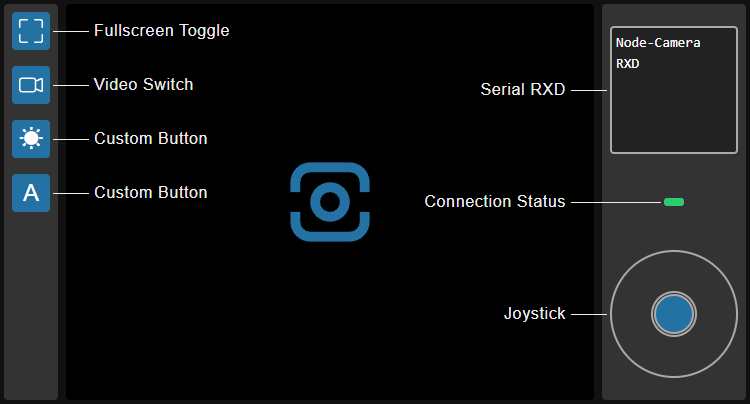
}The example configures the joystick for Steering & Drive mode ("joy_mode": 2), and configures the steering servo ("steering") and the drive servo ("drive"). The button array ("buttons") defines two buttons. The first self-locking button (☀), controls the LED switch through commands. The second normal button (A), transmits the string "hello" to the Node-Camera serial port output (TXD) when clicked. The page also displays serial port RXD data ("rxd": 1).
The corresponding video console page is shown below:
Tools Panel
The Tools panel provides functions for testing, viewing system information, and managing configurations.
Tools
The Tools tab provides functional tests for capturing images, Serial-WebSocket bridge, network commands, and auxiliary functions such as I2C scanning and viewing system information. When UART Socket is enabled, the page will automatically establish a serial WebSocket connection.
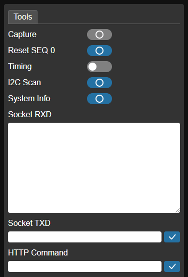
Capture - Photo capture test. Valid when Command Trigger is enabled. Clicking the button sends a capture command, triggering a single photo capture.
Reset SEQ - Resets the loop increment sequence number of captured photo filenames to
0.Timing - Capture timer switch. Valid when Timing Trigger is enabled. Controls the start/stop of the capture timer. When the timer is running, the Node-Camera captures photos at the interval set by Timing Interval sec.
I2C Scan - I2C address scanner. Enabled when the image sensor I2C port is exposed or an I2C Driver is configured. Clicking the button scans the I2C bus and displays the addresses of mounted devices.
System Info - View system information such as firmware name, version, MAC address, IP address, RSSI (signal strength in STA mode), and memory usage.
Socket RXD - Valid when UART Socket is enabled. Displays data received by the Node-Camera's serial port.
Socket TXD - Valid when UART Socket is enabled. Sends data via WebSocket, which is then passed directly to the Node-Camera's serial output.
HTTP Command - Used to test the HTTP command interface, for example,
flash=1(to turn on the LED).
Presets
The Presets tab allows you to reset the system, back up the current configuration, or load a saved configuration.
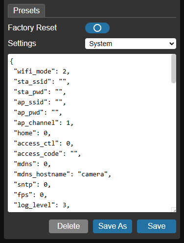
Factory Reset - Resets the Node-Camera to its default state (clears system configuration).
Settings - Select a configuration to operate from the drop-down list. This includes the system configuration (
System) and any saved configurations. Selecting a configuration displays its JSON content in the text box below. You can directly edit and save the configuration in the text box.Delete - Delete button. Deletes the selected configuration. The system configuration (
System) cannot be deleted.Save As - Save As button. Saves the configuration currently in the text box as a named backup configuration. The specified name will then appear in the Settings drop-down list. If you name the target configuration
System, it will overwrite the system configuration, allowing you to restore a backup to the system configuration.Save - Save button. Saves the configuration in the current text box to the selected configuration.